
The Erasmo project has successfully completed its first year thanks to the technical know-how, collaboration and contributions of the consortium partners. The automotive industry continues its transformation through the introduction of connectivity and vehicle automation, applications that are at the core of new business models, whereby Positioning, Navigation and Timing (PNT) information is at the very basis of these novel offerings. Within this context, the ERASMO project funded by the European Union Agency for the Space Programme (EUSPA) is developing localisation technologies for use in location dependent vehicle applications.
You’re probably thinking, ERASMO…that rings a bell but what was it exactly about?
The ERASMO project aims at developing the hardware and software for the localisation function that shall enable fully automated driving. The following 3 key topics are going to capture the essence of the consortium’s work:
- Firstly we will describe the ERASMO architecture and the technical requirements
- We will touch upon the integration of the GNSS chipset into the ERASMO OBU design for data acquisition; and
- We are expecting to share more insights into the algorithm for the ERASMO OBU that will be tested using real data.
The current note investigates the expected solution through the defined technical requirements and the proposed functional architecture.
The ERASMO Localisation System (LS) has been formulated in a vehicle and application agnostic way, and to the extent that this will be possible also in a hardware agnostic way. This will allow the ERASMO LS to be applicable to different types of vehicles and to become an integral part of localisation dependent vehicle navigation systems. The ERASMO LS will use signals from the Galileo constellation by means of a Global Navigation Satellite System (GNSS) chipset and combine information from the vehicle’s sensors with information from exteroceptive sensors that capture the immediate surroundings. Moreover, it will include a V2X communications capabilities for cooperative information exchange between vehicles and the infrastructure. The communications software integrates all the system components in a synchronized and robust manner. The ERASMO LS will also include GNSS-based high-precision and multi-sensor fusion algorithms to provide the connected autonomous vehicle with positioning integrity. The ERASMO LS will embed the solution by means of an innovative positioning OBU that will integrate the different system components. The resulting system will be integrated into test vehicles for evaluation and demonstration purposes. The commercial business plan and dissemination activities complete the set of activities. The ERASMO project will seek to provide the OBU with integrity information that can be used for autonomous driving tasks as well as enhanced vehicle pose estimations (position and orientations) of a vehicle when operating in real-time. It will combine state-of-the-art technologies and provide on-time, continuous and precise information to the various functions within the AV software stack with localisation function interfaces. The approach also considers safety critical applications related to Advanced Driving Assistance Systems (ADAS) that rely very much on positioning information.
An initial step to define the ERASMO LS’ System Requirements and its Functional Architecture consisted in defining the Operational Design Domain (ODD). An ODD defines the geospatial location and conditions under which the ERASMO LS is to operate. The ODD generally defines when, where, and under what conditions an automated vehicle is designed to operate. Several standards are emerging that define a vehicle’s ODD, mainly applicable to the deployment of AVs. The ODD classification used for the purpose of the ERASMO project is an interpretation of these developing standards as well as discussions that have taken place as part a related project. Different use cases in which a vehicle typically operates (urban, rural, etc.) have already been identified and will be leading to create a system that is able to operate in different situations, contexts and dynamic conditions. On a more technical level, work is also progressing to define the system model underlying the ERASMO LS; The system model data flow diagram is in progress and the device’s physical architecture is also taking shape. It will be composed of physical modules, devices, connection protocols and the data flow interactions with the external elements.
One year into the project, the interaction of the ERASMO LS and the different functions of a smart vehicle have been mapped, as shown in the relationship diagram below:
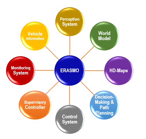
ERASMO supplies information to multiple functions within an autonomous vehicle
The system will use data/information as an input and/or output to the rest of the AV system. This diagram includes all the functions with which the ERASMO LS is expected to interact.
The relationships can be one or both ways with some functions sharing information or collecting it with other functions. For each of the related functions, it is important to state what is needed from the ERASMO LS, at what frequency and other functional information, further it is important to investigate and define appropriate levels of safety criticality. As work progresses, other requirements might emerge. We can, however, already provide an initial outline of these interfaces:
- Perception system – It generates data and information that is then used to feed the ERASMO LS algorithms. The algorithms will also process other information, such as the vehicle’s velocity and orientation, and the universal time to time-stamp data.
- World model – The ERASMO LS needs information in the form of the vehicle’s state. It is important to have both the position and orientation of the vehicle all the time.
- HD-maps – The ERASMO LS should periodically send its position to the HD-map system to extract the relevant information whenever maps are not consistently available in the system. A layer stored as part of the HD-maps will be fed to the ERASMO LS, which could be fed either for the entire trajectory or in the form of tiles. HD-map information provides contextual information (e.g., lane markings) but could also provide landmarks along the vehicle trajectory that can be used for localisation purposes.
- Decision-Making and Path Planning – The ERASMO LS will send the vehicle’s state, it is at times used as part of a feedback loop. The ERASMO LS could receive commands for the ERASMO LS management according to the needs of this system.
- Control System – The ERASMO LS will send the vehicle’s state at a high frequency. This is used for close-loop control that ensures the vehicle trajectory in a continuous manner.
- Supervisory Controller – This element provides information to the ERASMO LS that enables the control of its operation, such as start, standby, stop, and other standard operations that make up the working states of the ERASMO LS. Information coming from outside of the vehicle through the Communications Gateway is transmitted via the supervisory controller. Information that is shared outside the vehicle is sent first to this system that will then transmit it to the communications gateway for wireless transmission.
- Monitoring system – The operation of the ERASMO LS needs to be monitored to identify any malfunctions and perform checks to identify occasions in which outputs are providing information outside the expected ranges. The monitoring system could also obtain integrity estimates from the ERASMO LS which governs how the system should continue to operate, which could then be used to trigger a safety system.
Last but not least, the ERASMO LS will incorporate a High-Accuracy GNSS module (HA-GNSS) consisting of three main elements: two GNSS positioning algorithms, PE (PPP-RTK) and SPP, and the module managing the positioning and integrity solutions provided by them. A-GNSS Solution Manager provides the HA-GNSS PVTH+I final solution. The final solution HA-GNSS PVTH+I (High accuracy Global Navigation Satellite Systems, Position, Velocity, Heading and Integrity) is calculated based on the Position Estimation (using precise point positioning (PPP) and Real-Time Kinematic (RTK) ) and Single Point Positioning (SPP) technologies considering Protection Levels requirements for different Integrity Risks and taking into account the availability of PPP-RTK inputs (GNSS satellite orbits and clock corrections and phase measurements). The HIN PVTH+I (High Integrity Navigation data including Position, Velocity, Heading and Integrity information.) module is ultimately responsible for computing the integrity confidence levels from some of the input positioning information. It does so by combining all the positioning information received by the various sources and by providing the integrity layer, that is, the protection levels associated to the vehicle position for different Integrity Risks.
Did you find this interesting, informative and enlightening and cannot wait to learn more about this project? We will inform you about the latest developments here on LinkedIn, via Twitter and on the project’s website.
Thank you for following us and make sure to share this among your networks
#automotive #automateddriving #vehiclesensors #oems #autonomousvehicles #pnt #gnss #galileo #chipset #V2X #vehicleautomation #locationtechnology #ADAS #ERASMO_GNSS #erasmoenhancedreceiverforautonomousmobility